-40%
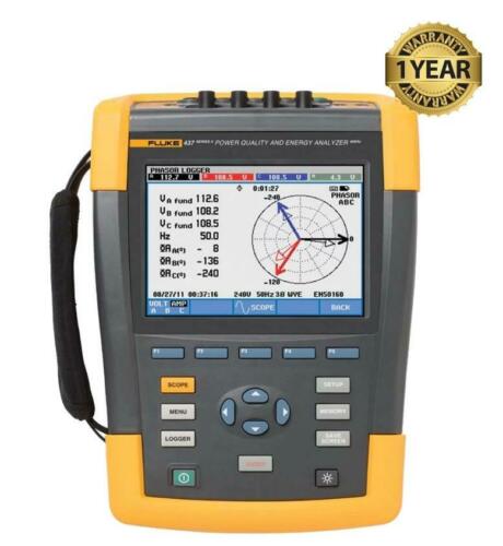
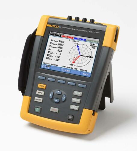
Fluke 437 Series II Three Phase Power Quality Analyzer Energy Meter 437-II 2
$ 4485.35
- Description
- Size Guide
Description
ebay templateThe Following Items Are Included:
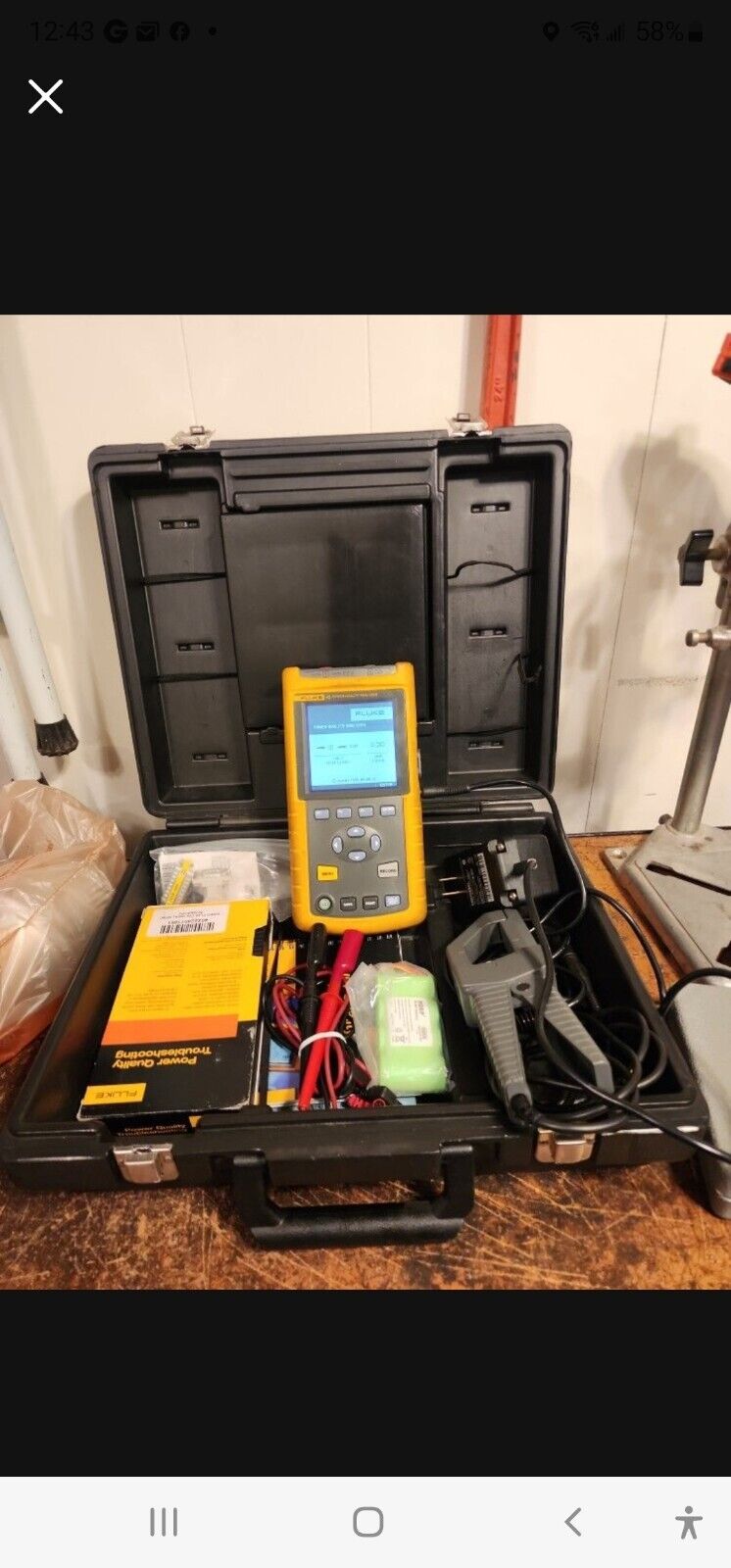
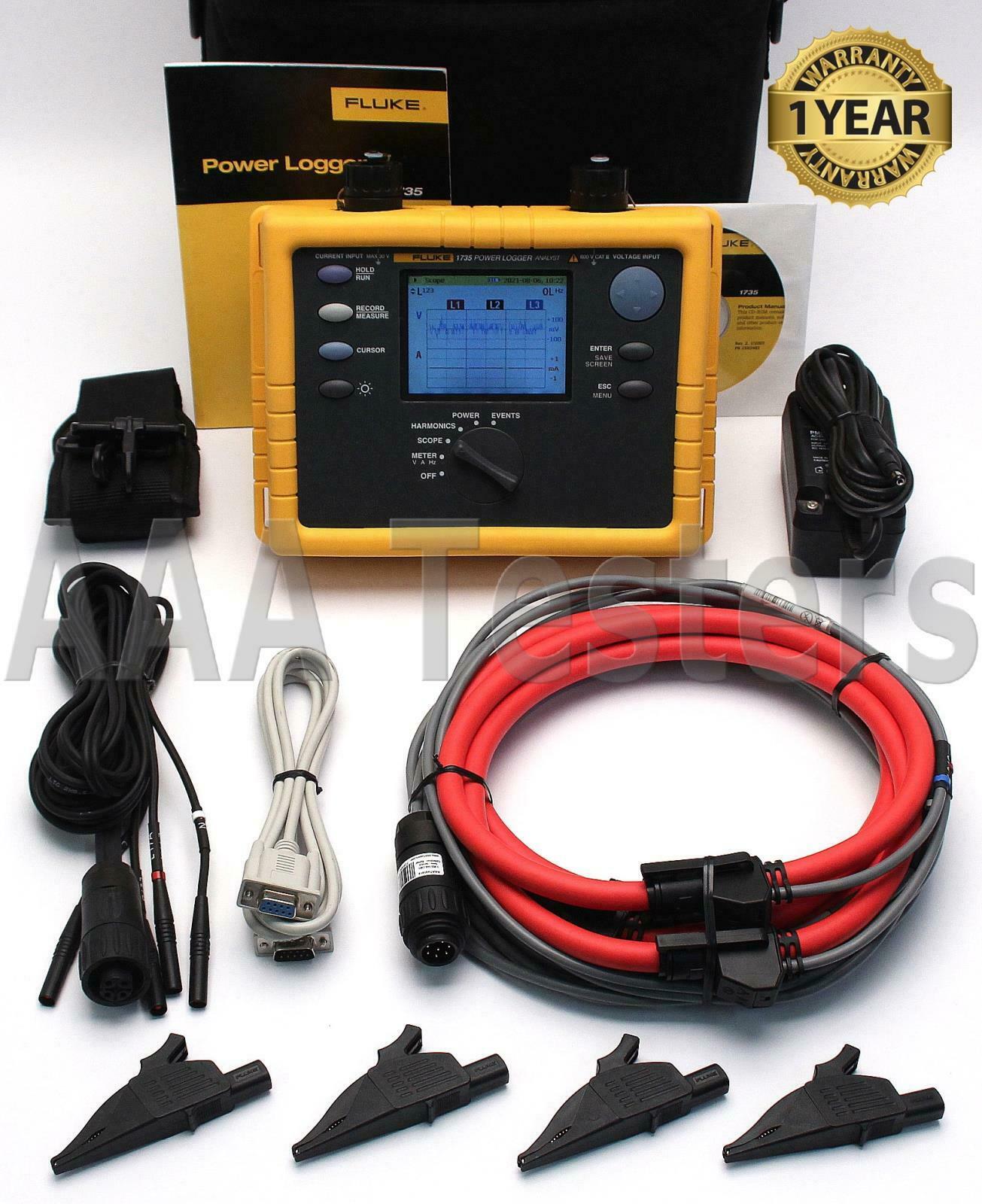
Fluke 437 Series II Three Phase Power Quality Analyzer (BC# -L/T*)
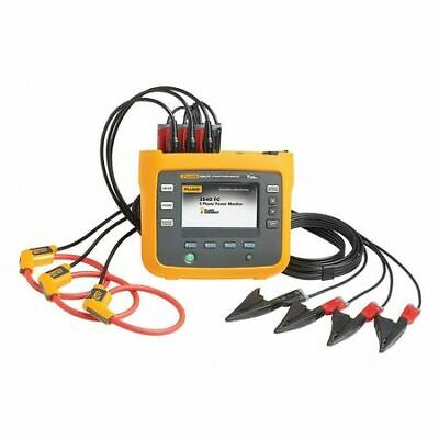
Fluke i430 Flex Cables
Test Leads
Fluke Alligator Clips
AC Adapter/Charger
USB PC Interface Cable
User Manual On Cd-ROM
Carrying Case (G)
BE SURE TO CHECK OUR EBAY STORE FOR OTHER ITEMS!
This Item Has A Current Calibration!
Fluke 437 Series II HandHeld Three Phase Power Quality Analyzer Energy Meter
Helps locate, predict, prevent, and troubleshoot power quality problems in three-phase and single-phase power distribution systems
Includes i430 Flex Cables, Carrying Case & Accessories As Listed Above!
Working Condition: Excellent
Condition: Refurbished
Calibrated: Yes
Warranty: 1 YEAR WARRANTY
Fluke 437-II 3 Phase Power Quality & Energy Analyzer
437 Series II Power Quality and Energy Analyzer
The Fluke 437 Series II Power Quality and Energy Analyzer is designed specifically for the defense and avionics industries. Equipped with all the functionalities of the 435 II including PowerWave, Power Inverter Efficiency and an Energy Loss Calculator, the 437 II goes one step further by measuring up to 400 Hz. The ability to measure at a higher frequency is necessary for those working in submarines, aircrafts, and other transport applications.
The new 430 Series II Three-Phase Power Quality and Energy Analyzers offer the best in power quality analysis and introduce, for the first time ever, the ability to monetarily quantify energy losses.
The new Fluke 434, 435 and 437 Series II models help locate, predict, prevent, and troubleshoot power quality problems in three-phase and single-phase power distribution systems. Additionally, these models feature revolutionary power quality and energy measurement functions that help facilities reduce electrical power consumption, and improve the performance and lifespan of electro-mechanical equipment. Below you will find brief descriptions of these new features.
Unified power measurement
Previously, only experts could calculate how much energy was wasted due to power quality issues; utilities could calculate the cost, but the required measurement process was beyond the reach of average electricians. With the new, patented Unified Power function of the 430 Series II, you can use one handheld tool to determine how much power is being wasted, and calculate exactly what the extra consumption costs.
Fluke’s patented Unified Power Measurement System provides the most comprehensive view of power available, measuring:
Parameters of Classical Power (Steinmetz 1897) and IEEE 1459-2000
Detailed Loss Analysis
Unbalance Analysis
These UPM calculations are used to quantify the fiscal cost of energy loss caused by power quality issues. The calculations are computed, along with other facility-specific information by an Energy Loss Calculator that ultimately determines how much money a facility loses due to wasted energy.
PowerWave data capture
For some users, loads switching is a cause of power quality problems. When loads switch on, the current draw sometimes causes the voltage to drop to a level that causes other equipment to malfunction. The PowerWave function available in the 435 and 437 Series II models enables users to capture voltage, current and frequency signals simultaneously at a high speed to see which interaction is potentially causing problems.
PowerWave goes beyond standard power quality measurements; PowerWave’s fast data capture mode enables system dynamics to be characterized. Waveforms for voltage and current are continuously captured for the specified time, and are displayed on screen in high detail; the power waveform is derived from the data. In addition, half-cycle RMS values for voltage, current, power and frequency can be stored and retrieved for analysis. This feature is particularly useful for testing of standby generation systems and UPS systems where reliable switch-on can be vital.
Power inverter efficiency
Power inverters take dc current and transform it into ac current, or vice versa. Solar generation systems usually include an inverter that takes the dc energy from the solar cells and converts it to useful ac power. Inverters can lose performance over time and need to be checked. By comparing the input power with the output power you can determine the system efficiency. All 430 Series II models can measure the efficiency of such inverters by simultaneously measuring the dc and ac power of a system to determine how much power is lost in the conversion process.
400 Hz
By increasing the power frequency to 400 Hz, transformers and motors can be much smaller and lighter than at 50 Hz or 60 Hz, which is an advantage in aircrafts, submarines, space crafts, and other military equipment and hand-held tools. The 437 II model captures power quality measurements for these types of avionic and military systems.
Extensive data analysis possibilities
The Fluke 430 Series II analyzers provide two ways to analyze measurements. Cursors and zoom tools can be used for on-screen analysis of measurement data. Additionally, the stored measurements can be transferred to a PC with the included software to perform custom analysis and create reports. Measurement data can also be exported to common spreadsheet programs. Store hundreds of measurement datasets and screen captures for use in reports (depending on memory capacity).
Easy to use
Pre-programmed setups and user-friendly screens make power quality testing as simple as you would expect from Fluke. The high-resolution color screen updates every 200 ms and displays waveforms and wiring diagrams color coded to industry standards. Handy on-screen wiring diagrams for all commonly used three-phase and single-phase configurations guide you through connections.
Measures everything
Measure true-rms, peak voltage and current, frequency, dips and swells, transients, interruptions, power and power consumption, peak demand, harmonics up to the 50th, inter-harmonics, flicker, mains signaling, inrush and unbalance.
CAT IV 600 V and CAT III 1000 V safety rating
Designed to help protect you and your equipment, the Fluke 430 Series II analyzers and accessories are all certified to meet the stringent standards for use in CAT IV 600 V and CAT III 1000 V environments such as power connections and outlets throughout a low-voltage power distribution system.
Logger: record the detail you need
User-configurable, long-term recording of MIN, MAX and AVG readings for up to 150 parameters on all three phases and nuetral. Enough memory is available to record 600 parameters for over a year with 10 second resolution, or capture smaller variations with resolution down to 0.25 seconds. The logger function is quickly accessed by the LOGGER button, the simple step-by-step setup makes capturing your important measurements as easy as can be.
Automatic transient display
When using the 435 and 437 II models, every time an event or voltage distortion is detected, the instrument triggers and automatically stores voltage and current waveforms on all three phases and neutral. The analyzer will also trigger when a certain current level is exceeded. Hundreds of dips, swells, interruptions and transients can be captured this way. You can see voltage transients as high as 6 kV and as fast as 5 microseconds.
System-monitor: summary screen of overall power quality health
The MONITOR mode delivers a dashboard display of rms voltage, harmonics, flicker, interruptions, rapid voltage changes, swells, unbalance, frequency and mains signaling.
The dashboard is updated live, showing compliance of each parameter to EN50160 limits or your own limits. Color-coded bars clearly show which parameters are inside (pass) or outside (fail) limits. During a monitor session, you can easily drill down to more detail of any parameter to view and capture its trend for a report.
Fully Class-A compliant
The Fluke 435-II and 437-II are fully compliant with the new IEC 61000-4-30 Edition 2 Class-A standard. With this powerful capability, all measurements will be consistent and reliable in accordance with the latest international standard. Fluke’s Class A compliance, including time synchronization compliance has been independently verified, certification is available on request.
What is Class-A conformity?
Power quality measurement is a relatively new, and quickly evolving field. There are hundreds of manufacturers around the world with unique measurement methodologies. Whereas basic singleand three-phase electrical measurements like rms voltage and current were defined long ago, many power quality parameters were not previously defined, forcing manufacturers to develop their own algorithms. With so much variation between instruments, electricians tend to waste too much time trying to understand an instrument’s capabilities and measurement algorithms instead of understanding the quality of the power itself!
The new IEC 61000-4-30 Edition 2 Class-A standard takes the guesswork out of selecting a power quality instrument. The standard IEC 61000-4-30 Edition 2 defines the measurement methods for each parameter to obtain reliable, repeatable and comparable results. In addition, the accuracy, bandwidth and minimum set of parameters are all clearly defined. The 435 and 437 Series II models include flagging and available internal clock time-synching to fully comply with the rigorous requirements of Class A compliance. The Edition 2 standard includes a new class of instrument, Class S. While not as accurate as Class A instruments, Class S instruments such as the 434 Series II Energy Analyzer produce results that are consistent with Class A instruments.
Specifications:
Voltage inputs
Number of inputs
4 (3 phase + neutral) dc-coupled
Maximum input voltage
1000 Vrms
Nominal voltage range
Selectable 1 V to 1000 V
Max. peak measurement voltage
6 kV (transient mode only)
Input impedance
4 MΩ//5 pF
Bandwidth
> 10 kHz, up to 100 kHz for transient mode
Scaling
1:1, 10:1, 100:1, 1,000:1 10,000:1 and variable
Current inputs
Number of inputs
4 (3 phase + neutral) dc- or ac-coupled
Type
Clamp or current transformer with mV output or i430flex-TF
Range
0.5 Arms to 600 Arms with included i430flex-TF (with sensitivity 10x)
5 Arms to 6000 Arms with included i430flex-TF (with sensitivity 1x)
0.1 mV/A to 1 V/A and custom for use with optional ac or dc clamps
Input impedance
1 MΩ
Bandwidth
> 10 kHz
Scaling
1:1, 10:1, 100:1, 1,000:1 10,000:1 and variable
Sampling system
Resolution
16 bit analog to digital converter on 8 channels
Maximum sampling speed
200 kS/s on each channel simultaneously
RMS sampling
5000 samples on 10/12 cycles according to IEC61000-4-30
PLL synchronization
4096 samples on 10/12 cycles according to IEC61000-4-7
Nominal frequency
50 Hz, 60 Hz and 400 Hz
Display modes
Waveform display
Default display mode for Transients function Update rate 5x per second Displays 4 cycles of waveform data on screen, up to 4 waveforms simultaneously
Phasor diagram
Available in all modes via Scope waveform display
Default view for Unbalance mode
Meter readings
Available in all modes except Monitor and Transients, provides tabulated view of all available readings Fully customizable up to 150 readings for Logger mode
Trend graph
Available in all modes except Transients
Single vertical cursor with min max and avg reading at cursor position
Bar graph
Available in Monitor and Harmonics mode
Event list
Available in all modes
Measurement modes
Scope
4 voltage waveforms, 4 current waveforms, Vrms, Vfund. Arms, A fund, V @ cursor, A @ cursor, phase angles
Volts/amps/hertz
Vrms phase to phase, Vrms phase to neutral, Vpeak, V Crest Factor, Arms Apeak, A Crest Factor, Hz
Dips and swells
Vrms½, Arms½, Pinst with programmable threshold levels for event detection
Harmonics dc, 1 to 50, up to 9th harmonic for 400 Hz
Harmonics Volts, THD, Harmonic Amps, K factor Amps, Harmonic Watts, THd Watts, K factor Watts, Interharmonic Volts, Interharmonic Amps, Vrms, Arms (relative to fundamental or to total rms)
Power and energy
Vrms, Arms, Wfull, Wfund., VAfull, VAfund., VAharmonics, VAunbalance, var, PF, DPF, CosQ, Efficiency factor, Wforward, Wreverse
Energy loss calculator
Wfund, VAharmonics, VAunbalance, var, A, Loss Active, Loss Reactive, Loss Harmonics, Loss Unbalance, Loss Neutral, Loss Cost (based upon user defined cost / kWh)
Inverter efficiency (requires optional dc current clamp)
Wfull, Wfund, Wdc, Efficiency, Vdc, Adc, Vrms, Arms, Hz
Unbalance
Vneg%, Vzero%, Aneg%, Azero%, Vfund, Afund, V phase angles, A phase angles
Inrush
Inrush current, Inrush duration, Arms½, Vrms½
Monitor
Vrms, Arms, harmonic Volts, THD Volts, PLT, Vrms½, Arms½, Hz, dips, swells, interruptions, rapid voltage changes, unbalance and mains signalling.
All parameters are measured simultaneously in accordance with EN50160
Flagging is applied according to IEC61000-4-30 to indicate unreliable readings due to dips or swells
Flicker
Pst(1min), Pst, Plt, Pinst, Vrms ½, Arms ½, Hz
Transients
Transient waveforms 4x Voltage 4x Amps, triggers: Vrms ½, Arms ½, Pinst
Mains Signaling
Relative signaling voltage and absolute signaling voltage averaged over three seconds for up to two selectable signaling frequencies
Power Wave
Vrms½, Arms½ W, Hz and scope waveforms for voltage amps and watts
Logger
Custom selection of up to 150 PQ parameters measured simultaneously on 4 phases
Trend recording
Method
Automatically records min, max and average values over time for all readings being displayed for the three phases and neutral simultaneously
Sampling
5 readings/s continuous sampling per channel, 100/120** reading/s for 1/2 cycle values and Pinst
Recording time
1 hr up to 1 year, user selectable (default setting 7 days)
Averaging time
Minimum of 1 second
Memory
Data is stored on SDcard (8GB included 32GB max)
Events
Tabulated in event list, including 50/60** waveform cycles and 7.5s 1/2 cycle rms Voltage and Amps trend
Measurement method
Vrms, Arms
10/12 cycle contiguous non-overlapping intervals using 500/4162 samples per cycle in accordance with IEC 61000-4-30
Vpeak, Apeak
Absolute highest sample value within 10/12 cycle interval with 40 μs sample resolution
V Crest Factor
Measures ratio between the Vpeak and Vrms
A Crest Factor
Measures ratio between the Apeak and Arms
Hz
Measured every 10 sec in accordance with IEC61000-4-30. Vrms½, Arms½ Value is measured over 1 cycle, commencing at a fundamental zero crossing, and refreshed each half-cycle.
This technique is independent for each channel in accordance with IEC 61000-4-30
Harmonics
Calculated from 10/12-cycle gapless harmonic group measurements on Voltage and Amps according to IEC 61000-4-7
Watt
Full and fundamental real power display. Calculates average value of instantaneous power over 10/12 cycle period for each phase. Total Active Power PT = P1 + P2 + P3.
VA
Full and fundamental apparent power display. Calculates apparent power using Vrms x Arms value over 10/12 cycle period.
var
Fundamental reactive power display. Calculates reactive power on fundamental positive sequence components. Capacitive and inductive load is indicated with capacitor and inductor icons.
VA Harmonics
Total disturbance power due to harmonics. Calculated for each phase and for total system based upon total apparent power and fundamental real power
VA Unbalance
Unbalance power for total sytem. Calculated using symmetrical components method for fundamental apparent power and total apparent power.
Power factor
Calculated total watt/VA
Cos
Cosine of angle between fundamental voltage and current
DPF
Calculated fundamental Watt/VA
Energy/energy cost
Power values are accumulated over time for kWh values. Energy cost is calculated from user defined /kWh cost variable
Unbalance
The supply voltage unbalance is evaluated using the method of symmetrical components according to IEC61000-4-30
Flicker
According to IEC 61000-4-15 flickermeter—functional and design specification. Includes 230 V 50 Hz lamp and 120 V 60 Hz lamp models
Transient capture
Captures waveform triggered on signal envelope. Additionally triggers on dips, swells, interruptions and Amps level
Inrush current
The inrush current begins when the Arms half cycle rises above the inrush threshold, and ends when the Arms half cycle rms is equal to or below the inrush threshold minus a user-selected hysteresis value. The measurement is the square root of the mean of the squared Arms half cycle values measured during the inrush duration. Each half-cycle interval is contiguous and non-overlapping as recommended by IEC 61000-4-30. Markers indicate inrush duration. Cursors allow measurement of peak Arms half cycle.
Mains signaling
Measurements are based on: either the corresponding 10/12-cycle rms value interharmonic bin or the rms of the four nearest 10/12-cycle rms value interharmonic bins per IEC 61000-4-30. Limit setup for Monitor mode follows EN50160 standard limits.
Time synchronization
Optional GPS430-II timesync module provides time uncertainty ≤ 20 ms or ≤ 16.7 ms for time tagging of events and time aggregated measurements. When synchronization is not available, time tolerance is ≤ 1-s/24h
General specifications
Case
Design Rugged, shock proof with integrated protective holster
Drip and dust proof IP51 according to IEC60529 when used in tilt stand position Shock and vibration Shock 30 g, vibration: 3 g sinusoid, random 0.03 g2 /Hz according to MIL-PRF-28800F Class 2
Display
Brightness: 200 cd/m2 typ. using power adapter, 90 cd/m2 typical using battery power
Size: 127 mm x 88 mm (153 mm/6.0 in diagonal) LCD
Resolution: 320 x 240 pixels
Contrast and brightness: user-adjustable, temperature compensated
Memory
8GB SD card (SDHC compliant, FAT32 formatted) standard, upto 32GB optionally Screen save and multiple data memories for storing data including recordings (dependent on memory size)
Real-time clock
Time and date stamp for Trend mode, Transient display, System Monitor and event capture
Environmental
Operating temperature
0 °C ~ +40 °C; +40 °C ~ +50 °C excl. battery
Storage temperature
-20 °C ~ +60 °C
Humidity
+10 °C ~ +30 °C: 95% RH non-condensing
+30 °C ~ +40 °C: 75% RH non-condensing
+40 °C ~ +50 °C: 45% RH non-condensing
Maximum operating altitude
Up to 2,000 m (6666 ft) for CAT IV 600 V, CAT III 1000 V
Up to 3,000 m (10,000 ft) for CAT III 600 V, CAT II 1000 V
Maximum storage altitude 12 km (40,000 ft)
Electro-Magnetic-Compatibility (EMC)
EN 61326 (2005-12) for emission and immunity
Interfaces
mini-USB-B, Isolated USB port for PC connectivity SD card slot accessible behind instrument battery
For full Fluke 437-II Power Quality Logger product specifications, please click here:
Fluke 437-II
Please check our Huge Inventory with savings of up to 80% off of retail on Cat5/5e/6 LAN Cable Certifiers and Fiber Optic OTDR's, Fusion Splicers, CATV Meters, Fiber Optic Kits, Sources, Meters, Tools, Network Analyzers and much more. Here is a Link to our
Ebay Test Equipment Store
. All of our Test Equipment is backed with a Full Warranty and unbeatable customer support & service. Please don't hesitate to
contact us
for a Quote on Something you don't see in our inventory, sometimes we have items that may have not been listed or processed yet.
Test Equipment Store Offers a wide range of Refurbished Telecom/ Datacom Tools and Test Measurement Equipment. Which includes Fiber Optic Test and Splicing tools, Fusion Splicers, OTDRs, Copper and Fiber Cable Certifiers, CATV Test Equipment, Cable and Antenna Analyzers, Network Analyzers and much more!
We carry a large inventory of quality refurbished and used test equipment from all the major manufacturers. If you are looking for multiple quantities or if we don't have a listing for a particular item that you are looking for. Please contact us as it may be fresh inventory waiting to be listed or we'll be glad to find it for you at the best price possible and put up an eBay listing for you!
We Ship World Wide!
We will attempt to ship your item(s) within 24 hours after payment has been received. To get a real-time shipping quote to your destination, enter your country and zip / postal code information into the shipping calculator and click "Get Rate".
Many countries impose their own customs, duties, tariffs, taxes, etc. on items being shipped from a foreign country. We do not cover those cost's and we recommend that you contact your countries customs agency for that information.
We Offer Multiple Quantity Price & Shipping Discounts, Email Us If You Are Interested In Larger Quantities.
We accept credit card payment transactions via the online checkout system! The checkout process is designed so that it communicates with the merchant to confirm that payment has been made and cleared. Other methods of payment are outlined through the online checkout process. Winning bidders must contact us within 3 days after auction close if special payment arrangements are needed.
Your payment is expected within 5 days after the auction close. Unpaid auctions will be forfeited after 5 days of the auction close and the Item(s) will be relisted for sale.
Items will be shipped within 24 hours (1 Business Day) upon receipt of payment from the winning bidder. (Certain orders may take longer for processing due to comprehensive final service inspections)
A Shipment Tracking number(s) will be provided to inform Buyers of their expected ETA (Estimated Time of Arrival). Tracking number(s) will be provided the same day as order shipment.
Thank you
ALL MAJOR CREDIT CARDS & PayPal ACCEPTED
Sell Smarter with
Kyozou
.
Inventory and Ecommerce Management
